This session was about FAB Insystem Programmer The FabISP is an in-system programmer for AVR microcontrollers, designed for production within a FabLab.
That is, it allows us to program the microcontrollers on other boards we make, using nothing but a USB cable and 6-pin IDC to 6-pin IDC cable. It's based on the USBtiny and V-USB firmwares, which allow the ATtiny44 to perform USB communication in software. Programming can be done through avrdude.
The schematic (PDF) is super simple: USB connector, ATtiny44, and 6-pin ISP header, with assorted passive components. I started with the Eagle files for the USBtinyISP, although there's almost nothing left of it. Most of the parts for the FabISP are in the FabLab inventory. Exceptions include the Mini-B USB connector (SparkFun, Digi-Key), 12 MHz crystal (Digi-Key), and 18 pF capacitors for the crystal (Digi-Key).
Assignment-FAB ISP PCB milling using Modella
Fab ISP design layout
to create a design layout we can use softwares like Eagle,Kokopelli ,the file will be .png format,here is Fab ISP design layout downloaded from this following link,Mr.Luciano shared the link via slack,
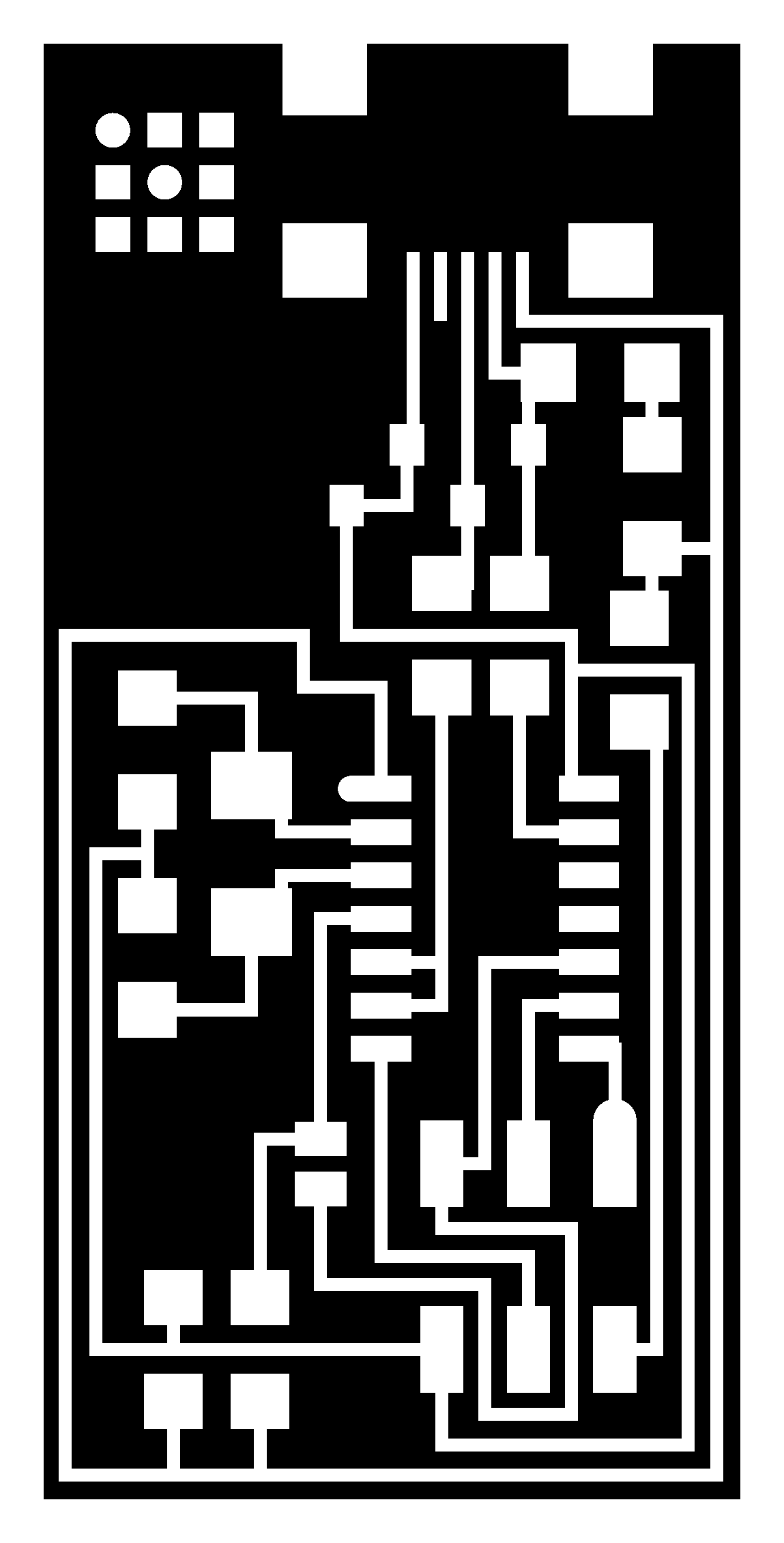

Downloaded fab isp labelled diagram from

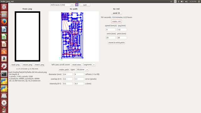
next step was loading the png using fab modules,The fab modules provide a set of software tools for personal fabrication, intended for use with machines common to fab labs.After installing the Fab modules, next select input and select file type as “.png” and the output as “Roland Modela MDX-20”. then loaded the png file,select make path,put the the offse value as 4,diameter as 0.4,now i am able to see the path thr0ugh which milling going to happen,put x and y as 20 to move the drilling bit and set the the position,next manually adjusted the z axis by pressing the down arrow,selected the bit 1/64 as i want to mill the traces first,
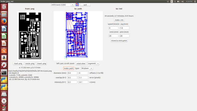
Now its all ready to go,Click on the “Make .rml” button and send the machine file to the Modela by clicking on “Send It!”.. After which the machine will start milling and removing copper from around the traces.
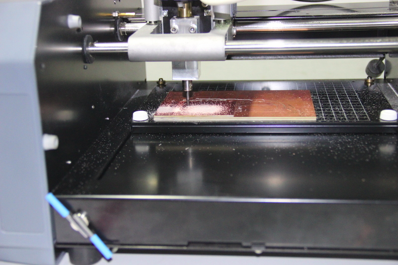
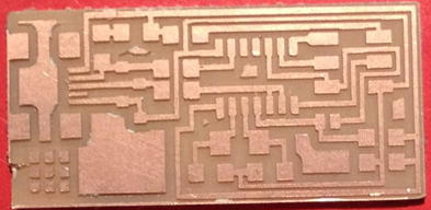
after milling the traces,next step was to cut the pcb from copper board ,for that i, had to change the bit first ,now i chose 1/32 bit loaded the cutout image then repeated the steps to set the bit and xyz plane,made the path,set diameter and offset,now pressed the make rml,now its ready to mill,the pressed start milling....This is my fabisp pcb after milling,even though it doesn't look perfect...its fine..
Soldering FAB ISP
This is my first soldering experiance, Soldering is the process of using a filler material (solder) to fix components in pcb sheet. Soldering occurs at relatively low temperatures (around 400 degrees Fahrenheit) as compared to brazing and welding, which actually melt and fuse the materials themselves at higher temperatures.
In soldering the filler material becomes liquid, coats the pieces it is brought into contact with, and is then allowed to cool. As the solder cools it hardens, and the two materials are joined. Soldering is a quick way to join many types of materials, from copper pipe to stained glass. It creates an electrically conductive strong bond between components that can be re-heated (desoldered) if you should ever want to disconnect two items joined together. It's great for joining electrical components and wires and is used in just about everything electronic.
To solder the FAB ISP i downloaded the fab isp labelled board diagram from this link so that i can see what components you need to and where to place them on the board.
http://academy.cba.mit.edu/classes/embedded_programming/hello.ISP.44.png!
i listed all the components required based on above labelled diagram
1 ATTiny 44 microcontroller
1 Capacitor 1uF
2 Capacitor 10 pF
2 Resistor 100 ohm
1 Resistor 499 ohm
1 Resisto### Introduction to FAB ISP
This session was about FAB Insystem Programmer, The FabISP is an in-system programmer for AVR microcontrollers, designed for production within a FabLab. That is, it allows us to program the microcontrollers on other boards we make, using nothing but a USB cable and 6-pin IDC to 6-pin IDC cable. It's based on the USBtiny and V-USB firmwares, which allow the ATtiny44 to perform USB communication in software. Programming can be done through avrdude. The schematic (PDF) is super simple: USB connector, ATtiny44, and 6-pin ISP header, with assorted passive components. I started with the Eagle files for the USBtinyISP, although there's almost nothing left of it. Most of the parts for the FabISP are in the FabLab inventory. Exceptions include the Mini-B USB connector (SparkFun, Digi-Key), 12 MHz crystal (Digi-Key), and 18 pF capacitors for the crystal (Digi-Key).
Soldering FAB ISP
This is my first soldering experiance, Soldering is the process of using a filler material (solder) to fix components in pcb sheet. Soldering occurs at relatively low temperatures (around 400 degrees Fahrenheit) as compared to brazing and welding, which actually melt and fuse the materials themselves at higher temperatures. In soldering the filler material becomes liquid, coats the pieces it is brought into contact with, and is then allowed to cool. As the solder cools it hardens, and the two materials are joined. Soldering is a quick way to join many types of materials, from copper pipe to stained glass. It creates an electrically conductive strong bond between components that can be re-heated (desoldered) if you should ever want to disconnect two items joined together. It's great for joining electrical components and wires and is used in just about everything electronic.
To solder the FAB ISP i downloaded the fab isp labelled board diagram from this link so that i can see what components you need to and where to place them on the board.
http://academy.cba.mit.edu/classes/embedded_programming/hello.ISP.44.png!
diagramComponent Marking Notes:
i listed all the components required based on above labelled
1 ATTiny 44 microcontroller
1 Capacitor 1uF
2 Capacitor 10 pF
2 Resistor 100 ohm
1 Resistor 499 ohm
1 Resistor 1K ohm
1 Resistor 10K
one 6 pin header
1 USB connector
2 jumpers - 0 ohm resistors
1 Cystal 20MHz
two Zener Diode 3.3 V
one usb mini cable
one ribbon cable
two 6 pin connectors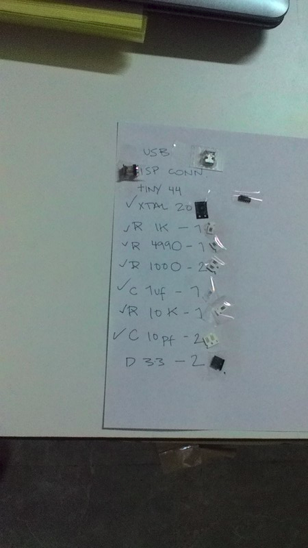
stuffs i used for soldering
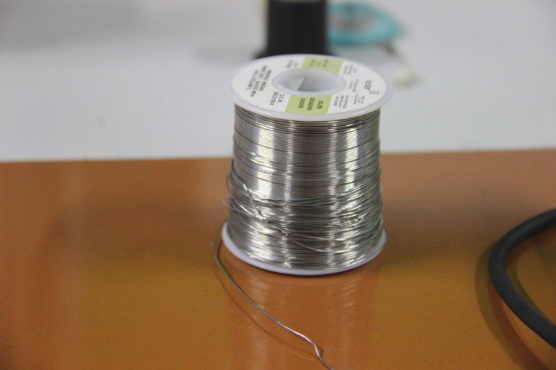
1 .Solder
2 .soldering iron
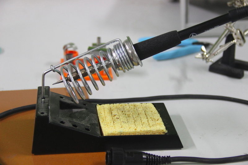
3 .Heat gun (to desolder any component)
As my instructor luciano insisted i started with small components like resistors,capacitors, If you haven't soldered before, it's probably good to practice with the smaller components (e.g. resistors and capacitors) before trying the microcontroller.
The USB connector was probably the hardest, because the traces are so narrow. I did the ISP header at the end, so it didn't get in the way when i was trying to solder other components. Most of the components was able to oriented either way, with the exception of the microcontroller (the circle marking pin 1 should be in the lower left) and the zener diodes,
Troubleshooting Short Circuits:
To find soldering errors,i used digital microscope to do a visual inspection of the board and reflow any solder joints that look cold (not shiny and smooth).The mini USB header wasn't in a good form,so i had to resolder it.
Then, used multimeter and check all the connections to make sure that:
* power and ground are not connected
* there is not a short on the power line.
3 .Heat gun (to desolder any component)
As my instructor luciano insisted i started with small components like resistors,capacitors, If you haven't soldered before, it's probably good to practice with the smaller components (e.g. resistors and capacitors) before trying the microcontroller.
The USB connector was probably the hardest, because the traces are so narrow. I did the ISP header at the end, so it didn't get in the way when i was trying to solder other components. Most of the components was able to oriented either way, with the exception of the microcontroller (the circle marking pin 1 should be in the lower left) and the zener diodes,i forgot to take photographs during soldering,as we have got only 1 soldeing unit it was quiet busy during soldering process....
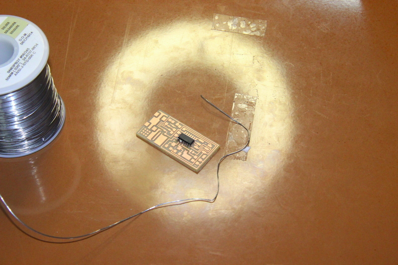
here is my fabisp after soldering....

Troubleshooting Short Circuits:
To find soldering errors,i used digital microscope to do a visual inspection of the board and reflow any solder joints that look cold (not shiny and smooth).The mini USB header wasn't in a good form,so i had to resolder it.
Then, used multimeter and check all the connections to make sure that:
- power and ground are not connected
- there is not a short on the power line.
Programming FAB ISP
This was quiet intresting,programming FAB ISP,To use FabISP as an ISP, it has to program first,To do this, i needed another (programmed) FabISP, some other in-system programmer (like an AVRISP mkII) or serial cable and dasa (level convertor) board.I used one of my collegues FABISP to program ATtiny44 in my FABISP.
As per the tutorial i closed SJ1 (the solder jumper near the microcontroller,after programming desoldered it to use my FABISP as a programmer) .Connected the 6 pin cable of the other programmer to my FabISP, made sure to orient it correctly (pin 1 to pin 1). to provide power to my FabISP used an USB cable connected to the computer .
To programm the FABISP first of all we had to install two softwares
- Avrdude (for programming AVR microcontrollers)
- GCC (to compile C code)
to install Get avrdude / GCC software and dependencies i used the following commands
sudo apt-get install flex byacc bison gcc libusb-dev avrdudesudo apt-get install gcc-avrsudo apt-get install libc6-dev
next step was download and unzip the firmware .for that i moved to the desktop then typed the below command
cd ~/Desktop
Downloaded the firmware from the Fab Academy Electronics Production page
wget http://academy.cba.mit.edu/classes/embedded_programming/firmware.zip
to Unzip the firmware
unzip firmware.zip
to do programming the board needs power ,to make sure that the mini USB connector for the FabISP trying to program is plugged into my computer AND that a separate pogramer is plugged in to the 6-pin programming header. (i used another working FabISP )

next step was editing the make file,for that i used the command
nano Makefile
To do the final step used this command - cd Desktop/firmware to navigate to the directory where i saved the FabISP firmware before
Next to compile the firmware.
make clean
make hex
make fuse
make program
finally it programmed,next i wnated Verify that is ISP working correctly:
- lsusb` in terminal ,then i got this window

Finally i have done it,after prograaming i removed solder bridge .